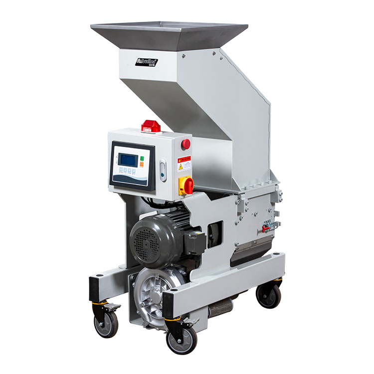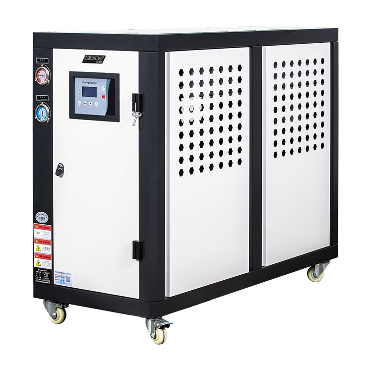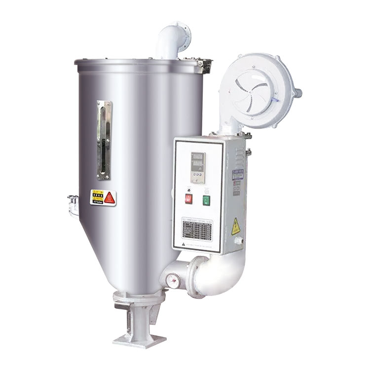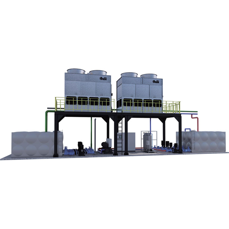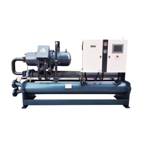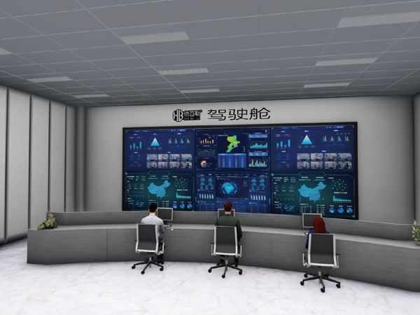
A closed-loop architecture represents a fundamental shift in industrial thermal management. This analysis explores the structural, hydraulic, and digital elements that define a modern Plastic Central Water Cooling System, focusing on how three-stage water treatment, siphon-assisted return, and MES connectivity converge to stabilize production quality and eliminate latent thermal variables. By examining the physics of mold cooling and the operational realities of large-scale manufacturing, the discussion outlines why conventional open towers no longer meet the precision demands of contemporary plastics processing.
Click on any section to jump directly to the topic.
- 1. How Does Closed-Loop Architecture Influence Industrial Thermal Stability?
- 2. Why Is Three-Stage Water Treatment Critical for Cooling Efficiency?
- 3. How Does Hydraulic Balance Redefine Pump Energy Consumption?
- 4. What Role Does Digital Visibility Play in Preventing Downtime?
- 5. Why Is Compressed Air Purging Indispensable During Mold Changes?
- 6. Frequently Asked Questions
1. How Does Closed-Loop Architecture Influence Industrial Thermal Stability?
The conventional approach to industrial cooling often treats water as a passive utility, pumped from an open tower without regard for its evolving chemistry. In reality, a carefully engineered Plastic Central Water Cooling System establishes a controlled thermal environment where mold temperature stability directly dictates cycle time and dimensional accuracy. By isolating the process water from ambient contamination, manufacturers transform cooling from a maintenance burden into a precise process instrument. The thermal dynamics of plastic injection molding rely heavily on the turbulent flow of coolant through narrow channels within the mold steel. When that coolant is drawn from an open cooling tower, it carries airborne debris, biological matter, and dissolved minerals that interact unpredictably with heat transfer surfaces. The closed-loop alternative removes these variables entirely.
Water cascades through an open tower, evaporates, and leaves behind concentrated minerals. The consequences are predictable: heat exchanger surfaces accumulate scale, biological films develop in warm wetted areas, and the water that eventually reaches a mold circuit carries a chemistry that no mold steel or small cooling channel was designed to tolerate. A closed-loop approach separates the process water from the atmosphere entirely. The same fluid circulates through the mold, returns to a heat exchanger, and is cooled without direct evaporation. The result is a water stream with minimal contamination, stable mineral concentration, and far less chemical intervention. The architectural distinction matters because mold cooling channels are not large industrial pipes; they are narrow passages, often with turns and restricted cross-sections, where a thin layer of deposit translates directly into a measurable change in heat transfer.
The Shift from Open to Closed Circuit Design
Closed recirculating systems are widely recognized as ideal for fouling control precisely because little or no contamination enters the loop, and the small make-up volume allows the use of high-quality treated water rather than whatever happens to be available at the plant intake. In practical terms, the cooling loop stops being a repository for whatever the water source contains and starts behaving like a controlled thermal circuit. There is no spray water in the process stream, no evaporation-driven concentration of dissolved solids, and no continuous introduction of airborne debris into the fluid that touches the mold. The separation is not a refinement of the open-tower concept; it is a different operating logic. The cooling tower still rejects heat, but it does so through a barrier that keeps the process water clean.
The protective effect of closed-loop architecture extends beyond scale prevention. A stable, clean water stream reduces the risk of under-deposit corrosion, maintains heat transfer coefficients closer to design values, and removes the need for frequent chemical shock treatment that can itself introduce variability. When water quality is no longer a moving target, mold temperature control becomes more repeatable, and cycle time deviations attributable to cooling drift become easier to isolate from other process variables. The cooling system stops generating noise in production data. In high-precision applications, where tolerances are measured in microns, the difference between a stable thermal boundary layer and a fluctuating one determines the success of the entire production run.
| Operating Dimension | Open Cooling Tower | Closed Cooling Tower |
| Process water exposure | Direct contact with atmosphere, airborne debris, and biological load | Sealed loop; process water isolated from ambient contamination |
| Mineral concentration | Rises through evaporation; scale risk increases over time | Stable; no evaporative concentration in the process stream |
| Mold channel condition | Progressive deposit buildup; heat transfer degrades | Clean channel geometry preserved; cooling performance remains predictable |
| Chemical treatment demand | Continuous biocide, antiscalant, and corrosion inhibitor dosing | Substantially reduced; chemistry managed through loop integrity |
| Water loss profile | Evaporation, blowdown, and drift losses | Minimal make-up; no evaporative loss from the process loop |
The comparison is not abstract. In plastics processing, cooling water quality directly influences thermal stability, dimensional consistency, and scrap rate. Deposits and bacterial films in water-carrying systems reduce heat exchange or block flow altogether, and the resulting thermal instability shows up as output loss and quality variation before it is recognized as a cooling problem. Closed-loop architecture removes that failure pathway from the process before it becomes visible on the production floor. The thermal inertia of the system is stabilized, allowing operators to fine-tune parameters without fighting the unpredictable behavior of a compromised fluid stream.
2. Why Is Three-Stage Water Treatment Critical for Cooling Efficiency?
Closed-loop design reduces the rate at which water chemistry degrades, but it does not eliminate the need to condition the water that enters the loop. A sealed circuit can still start with hardness minerals, suspended particles, or dissolved species that become problematic over months of circulation. The more robust configuration treats incoming water through multiple stages before it reaches the mold circuits, and then relies on the sealed loop to preserve that quality. This is the logic behind three-stage water treatment in the system: the objective is not merely to filter debris but to deliver water that will not precipitate scale-forming compounds on hot mold surfaces. Scale formation in cooling water is driven most commonly by the overconcentration of dissolved minerals, particularly calcium and magnesium salts whose solubility decreases as temperature rises.
In an open evaporative system, those minerals concentrate relentlessly. In a closed loop, the concentration remains stable, but if the initial fill water contains hardness at elevated levels, the loop still carries the potential for deposit formation at heat transfer surfaces. Multi-stage treatment addresses this by combining particulate removal with ionic conditioning. A representative three-zone approach uses progressive micro-filtration followed by an ion-exchange stage that targets calcium and magnesium, the leading contributors to hard-water deposits. The sequence matters: removing particles first protects the ion-exchange media, and the ionic stage then reduces the hardness burden that filtration alone cannot address.
Stainless Steel Tanks and the Hygiene Dimension
Water treatment is only part of the cleanliness equation. The tank that holds the loop inventory is also a wetted surface, and its material and geometry influence whether the system remains clean between treatment cycles. A stainless steel water tank offers a surface that is not prone to microbial growth, and its sealing characteristics limit the ingress of dust and impurities. The tank is flush with the ground, which simplifies cleaning and drainage and removes the concealed low points where stagnant water and sediment tend to accumulate. These are not cosmetic details. In a cooling loop that is expected to remain clean for months, every wetted surface either supports water quality or undermines it.
The practical outcome of combining closed-loop architecture, three-stage treatment, and hygienic tank construction is a mold circuit that does not scale. When mold flow channels remain free of deposit, the cooling performance designed into the tool is the cooling performance delivered in production. Cycle time remains stable, mold surface temperature distribution stays within the intended band, and the maintenance burden shifts from descaling and flow restoration to routine verification. The cooling system becomes a stable input to the molding process rather than a variable that must be continuously managed. This chemical stability also reduces the need for harsh cleaning agents, extending the lifespan of seals, valves, and pump components throughout the network.
3. How Does Hydraulic Balance Redefine Pump Energy Consumption?
Water quality determines whether the cooling loop can perform its thermal function over time. Hydraulic design determines how much pumping energy is required to make that happen. Many central cooling systems are over-pumped because the distribution layout forces the pump to overcome return-side losses that could have been avoided at the design stage. A surrounding waterway layout with balanced inlet pressure changes the hydraulic profile: return water arrives at the collection point with no residual suction pressure, and the pump is not required to pull against a vacuum. The design flow velocity becomes a deliberate parameter rather than a byproduct of pipe sizing. The Plastic Central Water Cooling System incorporates these principles to ensure that fluid dynamics work in favor of the process, not against it.
The more consequential hydraulic choice is the return strategy. A gravity-flow return in an enclosed workshop waterway allows the returning water to move under the influence of elevation difference, and when the return pipeline is gradually enlarged, the siphon effect becomes effective. The pump therefore does not waste head on a free-fall return; the return leg contributes to circulation instead of taxing the supply side. Energy audits consistently identify siphon-assisted return as a way to avoid wasting pumping head, and balanced system design as a route to lower pump power requirements. In a configuration where one pump produces the effect of two and energy consumption corresponds to half a pump, the savings are not a marginal tuning gain. They are the result of removing a hydraulic penalty that many systems carry by default.
Achieving Consistent Flow Velocity Across Parallel Circuits
Balanced inlet pressure and consistent flow velocity also support thermal uniformity. When every mold circuit sees a similar supply pressure, the flow split across parallel branches is more predictable, and the risk of one circuit starving while another is over-supplied is reduced. The design flow rate of 3 m/s is not an arbitrary figure; it is a velocity chosen to maintain turbulent heat transfer without imposing unnecessary friction loss. Combined with a return path that does not require the pump to overcome gravity, the hydraulic architecture delivers both energy efficiency and process stability from the same set of decisions.
Furthermore, the reduction of pump suction pressure to 0.0KG ensures that the mechanical seals within the pump are not subjected to unnecessary stress, which reduces wear and extends maintenance intervals. The fluid momentum is carefully managed through the surrounding waterway, allowing the entire network to operate at peak efficiency. When the system is properly balanced, the delta-T between supply and return remains consistent, providing a predictable thermal profile for every mold connected to the central loop. This level of control is impossible in an unbalanced system where pumps must constantly compensate for variable pressure drops across the manifold.
4. What Role Does Digital Visibility Play in Preventing Downtime?
A well-designed cooling loop can still fail silently if no one can see what is happening inside the channels. A partial blockage does not announce itself with an alarm in a conventional system; it manifests as a gradual increase in mold temperature, a subtle shift in cycle time, or a quality deviation that is attributed to other causes. The system addresses this visibility gap by combining real-time observation of water flow changes in the channel holes with a channel blockage prevention warning system. The warning system can be connected to computers and mobile phones through MES big data, which means the cooling loop becomes part of the plant’s digital operating picture rather than a stand-alone utility.
MES integration is most valuable when it connects cooling behavior to production context. Manufacturing execution systems already carry production plans, equipment states, and process parameters, and interfaces using OPC-UA or RESTful APIs can exchange this data at intervals measured in minutes rather than shifts. When cooling flow data is placed alongside mold identity, cycle count, and process setpoints, the question changes from "is the chiller running?" to "is this specific mold circuit behaving differently from its baseline?" That is a fundamentally more useful question, and it is the kind of question that prevents unplanned mold pulls rather than documenting them after the fact.
Automated Pressure Adjustment and Pump Failover
Digital visibility is only useful if the control layer can act on it. The system’s humanized design interface is intended to keep operation simple, while automatic pressure adjustment according to required power allows the loop to respond to demand without manual valve tweaking. When a system malfunction occurs, the water pump automatically switches and issues an alarm, which converts a potential production stoppage into a managed transition. Energy-saving start and stop logic for small auxiliary pumps and cooling towers extends the same principle to the thermal plant: equipment runs when the load justifies it, not because a fixed schedule says so.
Adjustable start and stop temperatures allow the system to avoid unnecessary operation across seasons, and the energy reduction that follows is a direct consequence of matching supply to demand rather than oversupplying by habit. The data generated by these operations is stored and analyzed, providing a historical record that can be used to refine maintenance schedules. If a specific mold consistently shows a slight increase in return temperature after a certain number of cycles, the MES can flag it for inspection before a complete blockage occurs. This predictive capability shifts the maintenance paradigm from reactive repairs to proactive interventions, ensuring that the central cooling system operates at peak performance without unexpected interruptions.
5. Why Is Compressed Air Purging Indispensable During Mold Changes?
Mold changes are a routine interruption, but they are also a moment when cooling circuits are opened, drained, and reconnected. Water left in a mold after disconnection creates conditions for rust and deposit formation during downtime, and spillage around the press introduces slip hazards and contamination. A compressed air purge sequence that flows from the inlet pipe to the mold and then out through the return pipe clears moisture from the internal passages before the mold is removed. The operation is simple, but its consequences are cumulative: molds are stored dry, cooling channels are less likely to develop corrosion products between runs, and the next production start begins with a clean circuit rather than a partially obstructed one.
Compressed-air purging also supports the broader discipline of keeping the closed loop closed. When a mold is drained with air rather than left to gravity-drain or blown off with shop air at the press, the risk of introducing contaminants into the circuit is reduced, and the water that is removed can be managed rather than lost to the floor. The technique is consistent with the same logic that governs the rest of the system: protect water quality, preserve channel geometry, and avoid interventions that create new problems while solving an immediate one. In a facility running dozens of mold changes per week, the cumulative time savings and reduction in maintenance overhead quickly become evident.
Maintaining Loop Integrity Between Production Runs
The integration of compressed air purging into the standard mold change protocol ensures that the Plastic Central Water Cooling System remains uncompromised by external factors. Even the most advanced water treatment and hydraulic design can be undermined if residual moisture is allowed to sit in a mold cavity for weeks. By systematically evacuating the lines, operators protect the investment in both the mold tooling and the central cooling infrastructure. The purging process is designed to be fast and efficient, minimizing the downtime associated with tooling changes while maximizing the operational lifespan of the cooling channels.
Furthermore, the dry state of the mold upon storage prevents the internal formation of galvanic corrosion cells, which are particularly damaging in molds constructed from dissimilar metals. Once the water is removed, the internal environment of the cooling channel is no longer conducive to the electrochemical reactions that degrade surface finish and restrict flow. When the mold is eventually reinstalled, the absence of rust and scale means that the initial flow rates and heat transfer coefficients match the original design specifications, ensuring a consistent start to the next production run.
6. Frequently Asked Questions
How does a closed cooling tower differ from a conventional open tower in daily operation?
What does three-stage water treatment actually remove from the incoming water?
Why does a gravity-flow return with siphon effect reduce pump energy?
Can the blockage warning system be integrated with an existing MES platform?
What is the purpose of compressed air purging during a mold change?
How does the plastic central water cooling system maintain consistent pressure across multiple production lines?
Ready to elevate your production standards? Discover how Simbler engineering can tailor a thermal management solution to your specific operational requirements.
contact us